
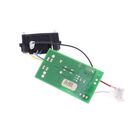
Dewalt 90639150 Trimmer SA PCB LST140
Description
Dimensions:
- Weight: 0.1 lbs
The Dewalt 90639150 Trimmer SA PCB LST140 supports electronic control operations in applicable lawn trimmers, helping process switching signals within the power and electrical system.
Common Symptoms:
• Trimmer remains inactive after switch input.
• Control response cuts out unexpectedly.
• Electrical terminals appear loose or damaged.
• Switch operation becomes delayed or inconsistent.
• PCB-related functions stop during operation.
Inactive Control Circuit
Quick Check: Operate the normal control and observe whether the trimmer produces any electrical response.
Fix Suggestion: Diagnose the control circuit and service the PCB assembly if it is identified as the fault source.
Prevention Tip: Keep electrical connectors seated securely during routine maintenance.
Unstable Electrical Response
Quick Check: Watch for repeated interruptions while using the trimmer's normal control input.
Fix Suggestion: Restore affected connections and address circuit faults associated with the PCB.
Prevention Tip: Keep wiring protected from rubbing against surrounding components.
Loose Circuit Connections
Quick Check: Examine accessible connectors for movement, damaged locking tabs, or poor seating.
Fix Suggestion: Reconnect affected terminals or renew damaged connection components as required.
Prevention Tip: Avoid pulling directly on electrical wires during service.
Delayed Switch Signals
Quick Check: Compare the timing of the trimmer's response after repeated switch activation.
Fix Suggestion: Trace the signal path and service the PCB when the delay originates within its circuit.
Prevention Tip: Have unusual control behavior addressed before continued heavy use.
Customer Experience: After installation, the PCB assembly processed the trimmer’s control signals properly, helping the electrical system respond to switch inputs during normal operation.

Customer Reviews
No reviews yet. Be the first to write one!
Write a Review
We strive to provide our customers with a hassle-free and efficient shopping experience. Our shipping policy ensures the timely delivery of your orders and complete customer satisfaction. View More
We are committed to ensuring your complete satisfaction with every purchase. We understand that circumstances may arise where you must return a product or request a refund. If for any reason you are not satisfied, you may return the item(s) according to the terms outlined below. View More
This Payment Policy outlines the terms and conditions governing all payments made for products purchased through our website. By making a purchase, you agree to be bound by this Payment Policy. View More